
| Engine : Electricity - 792/1386 |
|---|
| « Previous Question |
| Assuming the ladder diagram of figure "1" and the corresponding input/output diagram of figure "2" represents a simple PLC motor controller, what statement is true? EL-0232 |
| A) The input switch is a maintained contact on-off selector switch, output "A" is the motor contactor coil, and output "B" is a motor run status lamp for the running condition. |
| B) The input switch is a maintained contact on-off selector switch, output "A" is the motor contactor coil, and output "B" is a motor run status lamp for the stopped condition. |
| C) The input switch is a momentary contact start button, output "A" is the motor contactor coil, and output "B" is a motor run status lamp for the stopped condition. |
| D) The input switch is a momentary contact start button, output "A" is the motor contactor coil, and output "B" is a motor run status lamp for the running condition. |
loading answer...
Illustration EL-0232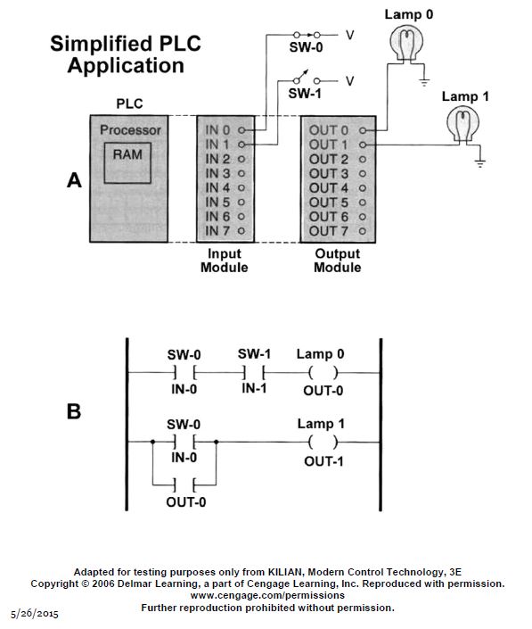
| Comments |
|---|
| fowen - 2018-10-09 19:58:02 Member (6) |
| In the drawings, what is happening is that SW-0 seems to be normally closed, SW-1 seems to be normally open. SW-0 is connected to IN 0, and SW-1 is connected to IN 1. If neither switch is actuated, the top rung is an AND function, so Lamp 0 is off. If SW-1 is actuated, then Lamp 0 will turn on. Lamp 0 is connected to OUT-0. So if OUT-0 is asserted (turned on), then Lamp-0 turns on. With the bottom rung, if SW-0 is not actuated, then Lamp 1 will turn on. Anyway, no question is posed regarding these figures, so it is hard to tell what the USCG is getting at besides confusing people. |
| fowen - 2018-10-09 19:52:12 Member (6) |
| I agree. How can such a question be posed and an acceptable answer be demanded when 1) There is no figure 1 2) There is no figure 2 3) There is no output A 4) There is no output B ????? |
| BergenAckerman - 2016-10-02 09:40:56 Expired Member (2) |
| This illustration does not match the question |
1
2
(2 pages)