
| Engine : Motor Plants and Auxiliary Boilers - 1302/947 |
|---|
| « Previous Question |
| A schematic diagram of an isochronous hydraulic governor is shown in the illustration. When the load is removed the speed increases, and the __________. Illustration MO-0100 |
| A) balance piston (piece 22) moves downward |
| B) flyweights (piece 8 and 9) move inward and the pilot valve (piece 10) moves downward |
| C) pilot valve (piece 10) moves upward |
| D) proportioner piston (piece 25) moves upward |
loading answer...
Illustration MO-0100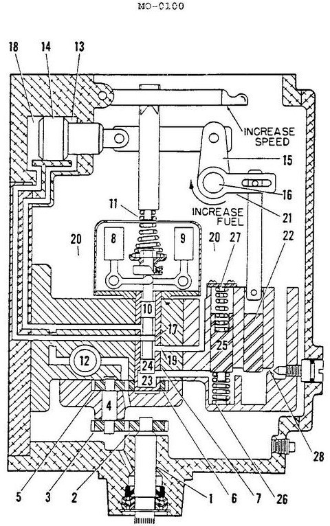
| Comments |
|---|
| There are no comments for this question. |