| Engine : Electricity - 470/1386 |
|---|
| « Previous Question |
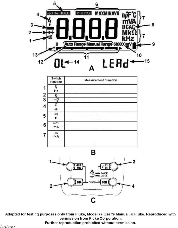
| As shown in figures "B" and "C" of the illustration, what should be the switch position and which test lead terminal jacks should be used if your intent is to measure DC currents anticipated as high as 200 milliamps? Illustration EL-0047 |
| A) switch position "6" and terminal jacks "1 and 4" |
| B) switch position "6" and terminal jacks "2 and 4" |
| C) switch position "7" and terminal jacks "1 and 4" |
| D) switch position "7" and terminal jacks "2 and 4" |
loading answer...
Illustration EL-0047